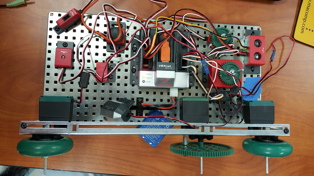
In this lab, we were given marbles of three different materials: wood, plastic, and metal. We were then challenged to sort the marbles by material using only materials contained in the VEX kit. Initially, we had intended to use a line follower to sort the marbles, which detects differences in color and light. The line follower proved too unreliable and difficult to work around, however, so we ended up just using physics. We used two motors: one to feed the marbles in and another to tilt the second ramp (first one from the left in the side view). Using a simple looped code, the feed would drop a marble. If it was metal, the weight would make it drop straight down into the first box from the right. The plastic and wood would continue moving on to the second ramp. The second ramp was set to tilt down to the right (based on the side view above) after a short period of time. The wood moved slower than the plastic, and so would be tipped back with the ramp, falling into the Chapstick container. The plastic would just blow through and fall into the large blue box on the end.
0 Comments
In this lab, we were challenged to build a fully-functioning elevator with three floors. It needed to be able to be summoned from each floor, return to the ground level after a period of inactivity, and have an override switch to bring the car back down to the ground. It also needed to have LED lights to indicate which floor the elevator was currently stopped at. We used a sonar to determine the height that the lift was at. Once it reached the height indicated by the button pressed, the motor stopped. The red light indicated that it was on the top floor, the yellow that it was on the second, and the green, visible in the front view, indicated that the lift was on the bottom floor. We had issues with our sonar reading correctly, and so we had to adjust its measurements and values for each day of coding. The coding was the most difficult part of the project. The code had to be clearly organized in order to tell exactly what function fell under which if statement. We ended up having if statements within if statements, and at one point, our font size was so small it could hardly be read. In the end, however, we got the elevator to work. The little green things that served as our chocolate in the cookie topper lab were out passengers, and they could reach any floor at any time they wanted.
The purpose of this lab was to design a machine that would feed "Cookies" (wheels, in this case) and drop "chocolate" (little green connector things; we aren't sure of the name) onto the cookies. The hardest part was designing a system to feed the cookies onto a conveyor belt, as the cookies got stuck on one another. In the end, we set them on a ramp and used a rubber gear to feed the cookies on the belt. Though not visible in the above images, two lights (one red and one green) are located in the middle. The red light is on while the belt is stationary, while the green is on while the machine is operating. The program starts when the bump switch is pressed, starting both the motor that drives the conveyor belt and the motor that feeds the cookies. Once a cookie is within 137 mm of the sonar, the belt stops and chocolate is dropped, utilizing another motor. The belt moves on, and the process starts over again. The hardest part of programming the robot was setting the correct distance for the sonar, as if the distance was too short, the chocolate would miss the cookie, but if it was too long, the chocolate would drop just because the belt moved.
For this project, the group built a test bed out of VEX components. We then worked on the basics of ROBOTC programming. We learned how to work the motors and servo, as well as the functions of the various digital and analog sensors.
This lab required us to make a self-propelling vehicle go 28 feet. The original constraints allowed for no ramps and nothing left behind save a counterweight. The group, however, had an original and creative idea, and the instructor allowed us to leave behind the majority of our mechanism. With a single axle, we had issues making our vehicle run straight every time, but guide walls along the ramp and chains used to make sure the ropes were centered helped solve the issue. In order to create motion, we wound a string around the center of the axle, which is connected to a chain and counterweight. When released, the counterweight causes the string to unwind. The vehicle drops and continues the motion, kind of like a yo-yo.
In this lab, we were challenged to make a vehicle that could propel itself a total of 20 feet, completely free of human force. Originally, our design had an insanely large mechanical advantage, but it required too much force to propel, so we decreased the IMA and increased the weight of our counterweight. We didn't actually make it the distance of 20 feet, with our maximum distance lying closer to 10 feet.
In this lab, we were challenged to build a compound machine using a trigger, a lever, and a wheel and axle in order to lift a weight at least five inches. Unfortunately, everyone in the group missed the part where we had to build a lever until the instructor pointed it out, so our final design is not as clear cut as we would have liked. The way the final design ended up working was that a lever at the top of the machine rotated to pull out an Allen wrench which served as our trigger. A weight consisting of one wheel and three large gears than falls and forcefully rotates the gears. When the machine is set, a loop is set over the large gear so that when the gear rotates, the loop slips off, as it is attached to a weight of three tires. The weight then pulls up the single tire about six inches by means of a pulley.
It is definitely not the neatest contraption, but it serves its purpose. Hi! In this lab, we were challenged to make a compound machine composed of 3 or more simple machines. The group ended up with one wheel and axle, two pulleys and belts, and one simple gear train. The whole machine had an IMA of 34.0816:1. This project involved investigating mechanical advantage provided by simple machines. For each simple machine (Inclined plane, wheel and axle, lever, and pulley), the ideal mechanical advantage (IMA) was calculated by dividing the distance of the effort by the distance of the resistance. |
Engineering
Throughout high school, I was in the STEM track. This is a collection of the various projects and products I created.